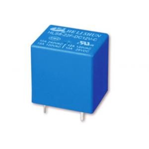
Miniature PCB relay 22F(OMRON G5L) SPDT 15A, 20.2*16.5*20.2mm
Description:
Relays allow one circuit to switch a second circuit which can be completely separate from the first. For example a low voltage battery circuit can use a relay to switch a 230V AC mains circuit. There is no electrical connection inside the relay between the two circuits, the link is magnetic and mechanical.
Single Pole Double Throw (SPDT):
Such relay consists of a pair of coil pins, a common pin, a normally open (NO) pin and a normally closed (NC) pin. When the relay is not activated, the common pin is in contact with the NC pin and when it is activated, the common pin will break away from contact with the NC pin and subsequently makes contact with the NO pin. Also, when the relay is deactivated (from activated state), the common pin will conversely break away from contact with the NO pin and return back in contact with the NC pin.
Features:
• Low coil power consumption
• High sensitivity.
• Small size, light weight.
• PC board mounting.
Applications:
Relays are used in electronics to switch a smaller current which in turn will control larger current. They prevent the user to have direct contact to the main device being controlled that might be holding high voltage. These devices are comparable to a remote c ontrol which is used to make a big electronic equipment work.
General data:
| Contact form | 1A 1C |
| Insulation resistance | 100MΩMin at500VDC |
| Dielectric strength between open contacts | 750VAC 50-60HZ(1 minute) |
| Dielectric strength between contacts and coil | 1500VAC 50-60HZ(1 minute) |
| Operate time | 10ms max. |
| Release time | 5ms max. |
| Ambient temperature | -40°C ~ +85°C |
| Shock resistance-Malfuction | 10G |
| Shock resistance-Destruction | 100G |
| Vibration resistance | 10-55Hz,1.5mm double amplitude |
| Ambient humidity | 40-85% RH |
| Weight | Approx 13g |
Coil data (@20°C)
| Rated voltage (VDC) | Coil Resistance Ω(±10%) | Max Operate Voltage (VDC) | Min Release Voltage (VDC) | Max Applied Voltage (VDC) |
| 0.36W | 0.51W |
| 3 | 25 | - | 2.25 | 0.15 | 3.9 |
| 5 | 70 | - | 3.75 | 0.25 | 6.5 |
| 6 | 100 | - | 4.5 | 0.3 | 7.8 |
| 9 | 225 | - | 6.75 | 0.45 | 11.7 |
| 12 | 400 | - | 9 | 0.6 | 15.6 |
| 24 | 1600 | - | 18 | 1.2 | 31.2 |
| 48 | 6400±15% | 4500±15% | 36 | 2.4 | 62.4 |
CAUTION:
1.The use of any coil voltage less than the rated coil voltage will compromise the operation of the relay.
2.Pickup and release voltage are for test purposes only and are not to be used as design criteria.
3.Unless otherwise stated, the rated coil voltage specified in coil parameter tableshall be used for all tests and its application to the relay
Outline dimension(mm):

PCB board layout and Wiring diagram: