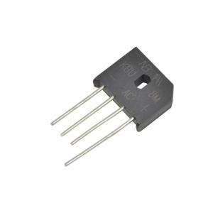
Through hole diode bridge rectifier KBU8M 8A 1000V single phase type
Description:
Bridge rectifier is a type of full wave rectifier which uses four or more diodes in a bridge circuit configuration to efficiently convert the Alternating Current (AC) into Direct Current (DC).
Rectifier circuits are classified into two major groups i.e., single phase and three phases. In both cases they are again classified into three main categories those are uncontrolled, half controlled and fully controlled. If we use diode to convert this voltage we can call that as uncontrolled, instead if we use power electronic components like SCRS we can call as controlled rectifiers. We can control half wave or full wave according to the application dependency.
Single-phase bridge rectifier is the most frequently-used circuit for electronic dc power supplies. It requires four diodes but the transformer used is not center-tapped and has a maximum voltage of VSM. The full-wave bridge-rectifier is available in three distinct physics forms. The main advantage of this bridge circuit is that it does not require a special centre tapped transformer, thereby reducing its size and cost. The single secondary winding is connected to one side of the diode bridge network and the load to the other side.
Features:
• Surage overload rating-200 amperes peak
• Ideal for printed circuit board
• Reliabe low cost construction utilizing molded plastic technique
• Plastic material has Underwriters Laboratory Flammability Classification 94V-0
• Compliant to RoHS
• Mounting position :Any
• Mounting torgue: 5 In.lb.max.
Advantages of bridge rectifier
• The rectification efficiency of full-wave rectifier is double of that of a half-wave rectifier.
• Higher output voltage, higher output power and higher Transformer Utilization Factor in case of full-wave rectifier.
• The ripple voltage is low and of higher frequency in case of full-wave rectifier so simple filtering circuit is required
• No center tap is required in the transformer secondary so in case of a bridge rectifier the transformer required is simpler. If stepping up or stepping down of voltage is not required, transformer can be eliminated even.
• For a given power output, power transformer of smaller size can be used in case of the bridge rectifier because current in both primary and secondary windings of the supply transformer flow for the entire ac cycle
Maximum ratings and electrical characteristics:
Rating at 25℃ ambient temperature unless otherwise specified. Resistive or inductive load,60HZ.
For capacitive load, derate current by 20%
| Characteristics | Symbol | KBU2M | Unit |
| Maximum recurrent peak reverse voltage | VRRM | 1000 | V |
| Maximum RMS bridge input voltage | VRMS | 700 | V |
| Maximum DC blocking voltage | VDC | 1000 | V |
| Maximum average forward rectified output current. @Ta=50°C | I(AV) | 8.0 | A |
| Peak forward surage current 8.3ms single half sine-wave super impossed on rated load(JEDEC method) | IFSM | 200 | A |
| Maximum forward voltage drop per bridge element at 2.0A/3.0A Peak | VF | 1.1 | V |
| Maximum reverse current at rated DC blocking voltage per element @Ta=25°C | IR | 10.0 | uA |
| Maximum reverse current at rated DC blocking voltage per element @Ta=150°C | IR | 1.0 | mA |
| Operating temperature rangeTJ | TJ | -55~150 | ℃ |
| Storage temperature range TA | TSTG | -55~150 | ℃ |
Dimension:(mm)